ECE 4110 Lab 5:
Configuring a
Linux Machine as a Router and Modifying the Operating System
Last Modified: Feb. 1, 2006
Due Date: Tuesday March 9, 2006
Please note this is a much longer lab than the others so please plan ahead and do not wait until the last minute to try to complete this lab. It can be done in pieces. You will not be able to complete this lab in one lab visit. Plan ahead and start early.
This
lab requires two computers. There are 3 lab setups (more, if needed) and no
reservations are required. Place your hard drive in a computer labeled “ECE4110
Lab 5 SOURCE.” The computer on your right should be labeled “ECE4110 Lab 5
DESTINATION a”
where a
is a number between 201 and 203.
IP
routing is the process that a machine containing multiple network interfaces
uses to decide where datagrams that it receives should to be delivered. We will
construct a router that connects three networks. The following diagram shows the networks and their
respective IP addresses.
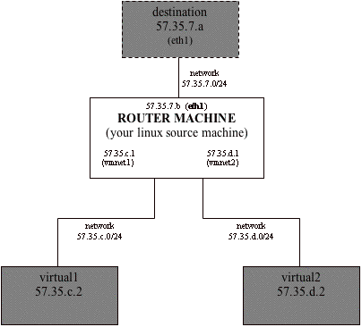




Part 1: A Virtual
Network
For lab 5 use the following numbering conventions:
|
Variable |
Value |
|
a |
The number
designated by your destination |
|
b |
The last number of
your RedHat WS 4 IP address |
|
c |
Your group number
plus 100 |
|
d |
Your group number
plus 200 |
The following steps will guide you in constructing the small network shown above. Rather than using three physical subnets, we will be using one physical subnet and two virtual subnets using the tool VMware.
Before you start this lab, you need to configure a new Network Interface Card (NIC). The Dell PC is using a Broadcom NIC (eth0), which we will not use in this lab. Instead we will use an Intel EtherExpress Pro100B NIC (run by eepro100 driver). The TAs have placed this new NIC inside each source and destination machine. There is no need for you to configure the destination machine. However, you will have to configure the source machine, which is the machine you will place your HD inside of.
After you power on the source machine, Linux should automatically detect the Intel NIC. During “Checking for the new hardware”, Kudzu (with a blue background) will ask what you would like to do about the new NIC. Choose “Configure” then select “Back” without filling in any network setup information. After the computer boots up, you will need to configure the new NIC. Login as the root. Click the RedHat icon, choose “System Settings” then choose “Network”. Right now, you should see eth0 is active. Click “Hardware”, if eth1 does not exist, then click “Add”. Choose “Ethernet” as hardware type. Click OK.
Choose EtherExpress Pro 100B as the adapter and “eth1” as the adapter, then click OK.
Click “Devices” then click “New”. Choose “Ethernet connection” as the “Device Type”. Click Forward. Select Ethernet Pro 100 (eth1), click Forward. Check “Statically set IP addresses”. Use 57.35.7.b (“b” is from the table above) as the IP address, and 255.255.255.0 as the subnet mask. Click Forward and click Apply. Finally, click Apply again. Now close the Network configuration window and save the settings.
Now, open /etc/modprobe.conf, add the follow line (right below “alias eth1 eepro100”)
options eepro100 options=0x50
(You have to change the line “alias eth1 ee100” to “alias eth1 eepro100” if it is not already done.) This is done to configure the network card into 10Mbs mode. We want to limit the bandwidth to only 10 mbits/sec for this lab. This will be a bandwidth bottleneck in your experiments.
Now, reboot your source machine.
You have already
installed VMware on your RedHat WS Host in a previous lab and should have
installed two RedHat WS 4 virtual machines as well. If not see the appendix of Lab 4 to see how to do this.
We are using VMware software
and only two machines instead of no VMware and four machines. This is just so
that we use as few real machines as possible in the lab leaving resources for
other classes.
We need to change the configuration of these two virtual machines for this lab:
From your WS4 Host machine, Run the vmware-config.pl
$ /usr/bin/vmware-config.pl
Use the following answers:
Accept the default directories for the first two questions.
Accept the default “yes” for the question about building a vmon module for your system.
Again accept the default directory for the location of the C header files.
“Would
you like to skip networking setup and keep you old settings as they are?”. No
Do you want networking for your virtual machines? Yes
Would you prefer to modify your existing network configuration using the wizard or the editor? Editor
Do you wish to make any changes to the current virtual networks settings? Yes
Which Virtual network do you wish to configure? (0-99)1
The network vmnet1 has been reserved for a host-only network. You may change
you sure you want to modify it? (yes/no) [no] Yes
What
type of virtual network do you wish to set vmnet1?
(bridged,hostonly,nat,none) [none] hostonly
Configuring a host-only network for vmnet1.
Do you want this program to probe for an unused private
subnet? (yes/no/help) [yes] No
What will be the IP address of your host on the private network? 57.35.c.1 (c is from table on page 2)
What will be the netmask of your private network? 255.255.255.0
The following
virtual networks have been defined:
. vmnet0 is bridged to eth0
. vmnet1 is a host-only
network on private subnet 57.35.c.0.
Do you wish to make additional changes to the current virtual networks settings ?(yes/no) [yes]yes
Which Virtual network do you wish to configure? (0-99)2
What
type of virtual network do you wish to set vmnet2?
(bridged,hostonly,nat,none) [none] hostonly
Configuring a host-only network for vmnet2.
Do you want this program to probe for an unused private
subnet? (yes/no/help) [yes] no
What will be the IP address of your host on the private network? 57.35.d.1 (d is from table on page 2)
What will be the netmask of your private network? 255.255.255.0
The following virtual
networks have been defined:
. vmnet1 is a host-only
network on private subnet 57.35.c.0.
. vmnet2 is a host-only
network on private subnet 57.35.d.0.
Do you wish to make additional changes to the current virtual networks settings ?(yes/no) [yes]no
Starting VMware services:
Virtual machine monitor
[ OK ]
Virtual ethernet
[ OK ]
Bridged networking on /dev/vmnet0 [ OK ]
Host-only networking on /dev/vmnet1 (background)
[ OK ]
Host-only networking on /dev/vmnet2 (background)
[ OK ]
What this has done is set up two virtual Host-Only Networks on /dev/vmnet1 and /dev/vmnet2. We are using the host-only networks to act like two independent subnetworks. Each virtual machine will act as if we are connecting it to an extra network card in the host.
Start VMware by typing vmware &. In another terminal type ifconfig. All of the host-only networks appear along with eth0 and eth1, functioning as if they were physical network cards.
Configuring RedHat WS 4 Virtual Operating Systems
Start both your WS4 virtual machines. Right click on the tab that lists the name of the machine, and go down to “Settings”. The setting for “Ethernet1” needs to be changed from “Bridged” to “Custom: Specific virtual network”. The drop down box then needs to be set to either /dev/vmnet1 or /dev/vmnet1 depending on the specific virtual machine. Check the network diagram on page 1.
Click on the RedHat Icon and go to System Settings -> Network. Click on Edit to modify your settings, and change your IP address and your gateway, if they were not setup accordingly (see network diagram on page 1 again). The gateway should be the IP of the host machine for the specific virtual network you are setting up.
Click OK. Then, click Deactivate, Activate, Apply. Close to change your settings.
Try pinging your host machine from each virtual machine.
$ping 57.35.c.1
$ping 57.35.d.1
Part 2: The Router
Setting up the Router
On the host machine:
To allow your host to forward or route IP packets, you need to type the following:
$echo
1 > /proc/sys/net/ipv4/ip_forward <ENTER>
This places a 1 in the file /proc/sys/net/ipv4/ip_forward. Check to make sure this command was successful by typing $cat /proc/sys/net/ipv4/ip_forward<ENTER> (1 should be printed on your screen). When Linux receives a packet, it looks at this file, and forwards if it sees a 1. This configuration is reset each time your physical machine is rebooted, so you must retype this command every time you reboot! Remember this throughout future labs.
To check where your physical machine will route packets, type the following:
$route –nv<ENTER>
You should now see the following routes included in your routing table (it may not be identical looking, but the routes should be there):
Destination Gateway Genmask Flags Metric Ref Use Iface
57.35.d.0 * 255.255.255.0 U 0 0 0 vmnet2
57.35.c.0 * 255.255.255.0 U 0 0 0 vmnet1
57.35.6.0 * 255.255.255.0 U 0 0 0 eth0
57.35.7.0 * 255.255.255.0 U 0 0 0 eth1
127.0.0.0 0.0.0.0 255.0.0.0 U 0 0 0 lo
0.0.0.0 57.35.6.1 0.0.0.0 U UG 0 0 eth0
Note that Linux has automatically added routes for the virtual network configurations.
**Note:
you will need to add routes on your destination machine, so it will know how to
forward the packets outside of its sub-networks (e.g. virtual_1 and
virtual_2).**
The route and ifconfig programs are both located in the /sbin directory. You can execute these programs directly because the /sbin directory is in your path. Type
$echo $PATH<ENTER>
to see what other directories are in your path. If /sbin were not in your path, you could execute these programs by typing $/sbin/route<ENTER> or $/sbin/ifconfig<ENTER>. This knowledge may be useful in future labs.
Some examples of manually modifying routes
Although it is not necessary go ahead and add an explicit host route with:
$route
add -host 192.168.161.149 vmnet1<ENTER>
To see this new entry, type
$route –nv<ENTER>
Now remove this extra entry
$route
del -host 192.168.161.149 vmnet1<ENTER>
Delete one of your needed existing net entries with
$route del -net 57.35.c.0 netmask 255.255.255.0 vmnet1<ENTER>
To see it is removed, type
$route –nv<ENTER>
Put it back since you need it
$route add -net 57.35.c.0 netmask 255.255.255.0 vmnet1<ENTER>
To see it is back, type
$route
–nv<ENTER>
For information on this command type
$man
route<ENTER>
**Note:
you will need to use route
command to add routes on your destination machine, so it will know
how to forward the packets outside of its sub-networks (e.g. virtual_1 and
virtual_2).** You will need to
figure out the routes, which you need to add. Also, delete the routes you added, before you log off the
destination machine (In case that your fellow classmates did not delete the
routes they added, you might need to delete them first.).
The
login for the destination machine is user: root and password: password
Manually Controlling Your Network Interfaces
Type ifconfig to see a list of your network interfaces.
Disconnect vmnet1 by typing
$ifconfig vmnet1 down<ENTER>
Now look at what this did by typing
$ifconfig<ENTER>
Put vmnet1 back with:
$ ifconfig vmnet1 57.35.c.2
netmask 255.255.255.0 broadcast 57.35.c.255 up<ENTER>
Again type
$ifconfig<ENTER>
For information on this command type
$man
ifconfig<ENTER>
For
part two of this lab, turn in the answer to this question:
Q. What other options can you configure about your network interface from the command line via ifconfig?
Confirm you are back where you started by typing route –nv and making sure that your routing table is as it was before you starting playing around with the networking commands.
Open VMware and start your two virtual machines. Confirm that you are able to ping the virtual machines from the router and that you can ping the router from the two virtual machines. Next ping one virtual machine from another. You have now set up your router successfully!
Print this routing table for both machines and include this in your lab turn-in. Explain every line in the routing table.
Part 3: Traffic Monitoring
In each of your WS4 virtual machines, open a new terminal and type:
$vmware-toolbox &<ENTER>
This will open the special VMWare OS tools that will help increase performance and improve results for this and future labs.
Make sure that RTC, floppy0, and sound are deselected. These unnecessarily utilize processing power.
Make sure that Ethernet0 and Time Synchronization are selected.
You must repeat these steps in every virtual machine and every time you restart a virtual machine! It is absolutely essential that you do this for future labs otherwise your results may not be acceptable.
Click the “Enter Quick Switch Mode” button (the far right icon on the VMWare Toolbar). This will increase the processing power given to your virtual machines and increase accuracy of data. You should have two tabs that will allow you to switch between your virtual machines.
Installation of Traffic Generators and Servers
Install your TCP generator executable onto virtual_1 and UDP generator executable onto virtual_2 by using sftp to copy from your physical host. For example, if your tcp_gen application is in the directory /root/lab2 on your physical host, type from your virtual machine:
$sftp 57.35.(c or d).1
enter root’s password
sftp>
get (location on host machine of the
files)
sftp>
quit
If you have any problems, consult man sftp. You should still have the executable code from previous labs; do not try to compile the source codes on any end station.
Log onto the destination computer next to you with the root account and password. Make a directory called “Group A” where A is your group number. Then sftp your tcp_sink and udp_sink executables to this directory.
Executing the Traffic
You will run the two traffic generators on your virtual machines so that all traffic is directed through the router. All of that happens on one physical computer enclosed in the dotted box in the lab figure. The router will forward the traffic to the other physical machine which is the destination. A bottleneck will be created because only 10Mbps of traffic can be transmitted out of your router, so the TCP and UDP generators will fight for this bandwidth.
The IP address of your destination host is as indicated by the diagram on the front of this lab.
Using the TCP and UDP traffic generators, record data to demonstrate how UDP can slow down TCP traffic so that TCP cannot get very much throughput. UDP traffic should cause the TCP traffic flow control mechanism to slow down the TCP throughput while UDP, which has no flow control mechanism, keeps transmitting at the same speed. You will need to record enough data to make graphs of your results.
UDP vs. One TCP Generator
(You have two virtual machines… run tcp_gen on one and udp_gen on another!)
Step 1: Start tcp_sink at your destination. Run tcp_gen by itself and note that it works as expected. Maximize the TCP throughput by decreasing the inter-arrival time and measure the maximum throughput recorded by tcp_sink. Remember that the important value is the quantity received at the destination, not the quantity sent at your source.
Step
2: Start udp_sink at your destination and run udp_gen by itself, noting that it
works as expected. Maximize the UDP throughput and record this value. Note that
because udp_sink requires reception of a termination packet in order to
calculate statistics, it may not be wise to set the interarrival time extremely
low. If the termination packet (the one with the special characters that the
sink is looking for to initiate printing statistics) is lost en route to your
destination, you will have to stop the sink and the gen, and start your trial
over. Q. Why this is not a problem for the tcp generator?
Step 3: Start the UDP traffic at a relatively low throughput (high interarrival time). Quickly start the TCP traffic generator with the inter-arrival time used in Step 1, and then stop it in about 30 seconds. Quickly stop the UDP traffic generator. Note that it is important to minimize the amount of time that both the UDP and TCP traffic generators are running, as this will result in errors for your results by including measurements when there is no contention. Record the throughput in Mbps as received by the destination of both UDP and TCP data.
Step 4: Slowly increment the attempted UDP throughput by decreasing the UDP interarrival time and repeating Step 3. Continue until virtually all TCP traffic has disappeared or you reach a UDP interarrival time below 0.8ms. Choose your interarrival times carefully so that one can see the effects of UDP and TCP traffic interaction. Many points showing the same distribution of UDP and TCP traffic is not educational. Your points should demonstrate the subtle effect of UDP traffic on TCP when there is a bottleneck. You should have at least 6 points to show the change.
UDP vs. Two TCP Generators
Note the maximum TCP throughput realized in step 1. Notice that the link capacity (10Mbps) is not completely utilized. This is because the TCP generator must wait for acknowledgement so doesn’t necessarily send packets as quickly as possible. Create two terminal windows in virtual_1, and from now on always run two TCP generators simultaneously. Add together the two throughputs to obtain your total TCP throughput. Using two TCP generators yields much better results than using just one TCP generator.
Repeat the previous experiment using the same UDP interarrival times, this time with two TCP generators.
TCP
vs. UDP
Repeat the previous experiment, except this time maintain a constant transmission speed for UDP and modify the interarrival times for your TCP generators. You should still be using two TCP generators, and each should use the same interarrival time. Use the same interarrival time points for the TCP generators as you uses for UDP generators in the first two experiments.
For Part 3 of this lab, create tables and graphs demonstrating the “undesirable” effect on TCP as a result of UDP traffic in the same network. On each of your graphs, place the attempted throughput (in Mbps) of the changing protocol (e.g. TCP) on the x axis, which can be calculated by dividing the average packet size by the attempted interarrival time. On the y axis, plot the actual transmission speed of both TCP connections (in Mbps), as was measured at the destination. Your lab should include at least three graphs from part three, and detailed explanations of your results. It is important that you explain both what is happening in the graphs as well as why. Discuss and explain reasons for similarities and differences between your three sets of results.
When you are done, please log out of your destination machine.
In part 3 of the lab, we saw that under normal networking conditions, UDP traffic will throttle TCP traffic. We will now look at a way to modify and recompile the linux kernel networking source code running in the router so that we can give priority to TCP. The proposed hypothesis is that this will “fix” our problem of TCP’s congestion mechanism being too nice in the presence of unfriendly UDP traffic. You will run some tests to see if this proposed hypothesis is correct or incorrect.
Part 4: printk
The objective of this part of the lab is to learn how to
modify the Linux kernel and how to recompile the Linux Kernel source code. You will print some messages from the
Linux Kernel and learn how to compile the kernel.
Background Setup:
Remember to enable IP forwarding each time you restart your physical machine by typing
echo 1 > /proc/sys/net/ipv4/ip_forward
Also, add the same routes on the destination machine as what you did in the lab5A.
Modifying the Kernel Code
Mount the 4110 NAS (login linux_class, password linux_class).
From the NAS Lab5 directory, copy the file kernel-2.6.9.EL.src.rpm to your home directory.
$ cp /mnt/nas/Lab5/kernel-2.6.9.EL.src.rpm ~/.
$ cd ~
$ rpm –ivh kernel-2.6.9.EL.src.rpm
$ cd /usr/src/redhat/SOURCES
$ bunzip2 linux_2.6.9.tar.bz2
$ tar –xvf
linux_2.6.9.tar
This will put all of the source code to the kernel in the directory:
/usr/src/redhat/SOURCES/linux_2.6.9/
Now we will modify the LINUX network implementation code on
your computer to print to the screen every time you route a UDP or a TCP
datagram. Print to the screen "UDP" for every UDP datagram routed,
and print "TCP" for every TCP datagram routed.
Make a backup copy of the file /usr/src/redhat/SOURCES/linux_2.6.9/net/sched/sch_generic.c This is the file that determines how packets will be
scheduled for routing, and is where in the routing process your computer
determines the packet type. The backup copy is necessary in case you make a
mistake.
Now use emacs or gedit to open: /usr/src/redhat/SOURCES/linux_2.6.9/net/sched/sch_generic.c
Near the beginning where all the other includes are, add:
#include <linux/ip.h>
and in the pfifo_fast_enqueue function add:
struct iphdr *iph = skb->nh.iph;
if(iph->protocol == IPPROTO_TCP){
printk("TCP\n");
}
if(iph->protocol == IPPROTO_UDP){
printk("UDP\n”);
}
Compiling the Kernel
Type the following commands:
cd
/usr/src/redhat/SOURCES/linux_2.6.9/
make
oldconfig (accept all the old defaults)
This command will save all of the options that are currently built into the kernel to a file (.config). This allows you to keep the current options you have selected and add to them, rather than erase the options you have previously turned on. Now type:
cp .config /root/.configold
make clean
make mrproper
It’s now time to configure the kernel.
Type make gconfig
Click File System;
select Ext3 journaling file system support as <y>
select DOS FAT fs support as <y>
select MSDOS fs support as <y>
select VFAT (Windows-95) fs support as <y>
Click Device Drivers->SCSI device support->SCSI low-level drivers;
Unselect all Qlogic support modules. (These cause compilation errors with the version of GCC we are using and are unneeded in our setup.)
Save this configuration and exit the tool.
Now we will build the kernel:
make clean
make bzImage
Make sure this compiles and does not cause any errors. If so, you will need to go back and edit your sch_generic.c file to correct the mistakes.
Each time from here on out that you change your C code
all you have to do is repeat make bzImage and go from there.
make
modules
make modules_install
You have created a new kernel image file, bzImage.
Now we will install it:
make install
Reboot the system and select Red Hat Enterprise Linux WS (2.6.9) as your kernel. Login.
Testing your Code
In order to see the “TCP” or “UDP” messages in part A of the lab, you need to type
echo 8 > /proc/sys/kernel/printk
This enables the printk messages to be written to the console. Remember to reenable IP forwarding.
VMWare must be reconfigured to use your new kernel. Run vmware-config.pl, and accept all the default module options (but do not change your networking setup). Run vmware.
If they are not already installed, sftp your tcp and udp sinks to your destination machine.
Turn on ip forwarding, open your virtual machines, open and configure vmware-toolbox on each virtual machine, and enter quick switch mode as you did in Lab 5A. Run the TCP traffic generator source on virtual1 and the sink on the destination. Generate roughly 3 Mbps of TCP traffic. Run the UDP traffic generator source on virtual2 and the sink on the destination. Generate roughly 7Mbps of UDP traffic.
printk() messages are written to a text console, therefore cannot be printed while in X Windows. You therefore need to switch to a virtual console to see your messages. On your host machine, Press <Ctrl>-<Alt>-<F1> to see the printk messages. To return to X Windows, press <Ctrl>-<Alt>-<F7>. (Note: it may be necessary to use the LEFT set of control and alt).
Demonstrate this printing to the screen to the TA to
receive a checkoff for part 4 of the lab.
Turn in a highlighted copy of a printout showing your modified kernel code for
/usr/src/redhat/SOURCES/linux_2.6.9/net/sched/sch_generic.c. This will go in your results for part 4 of the
lab. You may want to print this
now, as you will be changing this code in the next section.
Part 5: Changing the kernel scheduling
Modify the Linux kernel (the sch_generic.c file) so that all TCP traffic is placed in one queue
(the highest priority queue) and all other traffic into a second queue (a lower
priority queue). When your router sends packets, it will send from the TCP
traffic queue first, and only send form the second queue (with UDP traffic,
etc) when there is no TCP traffic to send. A print to the screen will slow your
kernel down and change your results so remove the printk statements from
part 4.
Requirement: When modifying your kernel, do not change the value of the variable priority in the IP packets themselves. Our special queues only apply to our router; some other router in the network may want to see the original value.
After recompiling and booting into the kernel, use your traffic generators to show how your code works and compare the results to what you wrote and concluded in part 3 which is an unmodified linux kernel. In your results, compare the effects of varying TCP and UDP traffic on the unmodified kernel from part 3 with the modified kernel from part 5.
Run two TCP traffic generator sources on virtual1 and the sink on your destination. Run the UDP traffic generator source on virtual2 and the sink on the destination.
In order to show your results for part 5, generate plots for the following two experiments:
1) Fix the TCP transmission rate to achieve maximum throughput and vary the UDP rate. Plot the actual (destination) UDP and TCP throughput (Mbits per second measured) versus the attempted UDP load. Use the same size packets but change your inter-arrival times in the traffic generator to change your atempted rate. Warning: Do not use the default value for the inter arrival time for TCP. This will only generate about 250 kbits/second which is too low to see the effects you are looking for. Use whatever yields as close to 10 Mbits/sec or so.
2) Fix the UDP transmission rate to achieve roughly 10Mbit/sec and vary the TCP rate. Plot the actual UDP and TCP throughput (Mbits per second measured) versus the attempted TCP load as input by you. Hint: For case 2, run both generators for a long time. You may receive acceptable results with 20 second runs, but they may take as long as a minute. Shut down the tcp_gens first and then quickly shut down the udp_gen (consider why this order is different from part 3). Make sure that all three generators are shut off in a very short period of time otherwise your results will be skewed.
On each graph, plot both your UDP throughput and TCP throughput, where the latter is the sum of your two TCP sinks.
What to turn in to the TA:
Be sure your report has the parts labeled with title pages so we can see which part is which in your turn in.
Part 1:
Nothing to turn in.
Part 2:
An answer to the Part 2 Question. Printout of routing tables from both source and destination computers with detailed explanation of every line.
Part 3:
For Part 3 of this lab, you should include at least three graphs, and detailed explanations of your results. It is important that you explain both what is happening in the graphs as well as why. Discuss and explain reasons for similarities and differences between your three sets of results.
Part 4:
Be sure you got a TA signoff (on the TA signoff sheet) of
your demonstration of Part 4 printing messages. Also turn in a printout of a
copy of your modified kernel code from Part 4 (only the part at which you
edited the code). Highlight the changes you made to the code with a marker of
some sort.
Part 5:
1)Detailed report on what experiments you ran and plots of results. Discuss the effects of TCP and UDP running at the same time, and what effect you had on this by modifying your router scheduling. Also, in addition to this, describe, compare, and contrast your graphs from part 3. This report must be typed and be very clear and conclusive. It is important that you explain not just what you noticed but why these effects occurred. You should have a total of at least 4 graphs (Modified and Unmodified kernels with fixed TCP and UDP) each with two lines (UDP and TCP throughput). If you are using Microsoft Excel, you should use a connected scatter plot. Your X-axis, the attempted throughput, should range from roughly 0Mbps to 15-20Mbps (or wherever the critical section of your graph exists). Did the proposed hypothesis of changing the scheduling fix the problems associated with running TCP and UDP at the same time? Explain.
2) Printout of a copy of your modified kernel code from Part
2 (only the part at which you edited the code). Highlight the changes you made
to the code. Call this Appendix One.
Please turn in your report to a TA.